

 3D
Project guides
Line-following robot
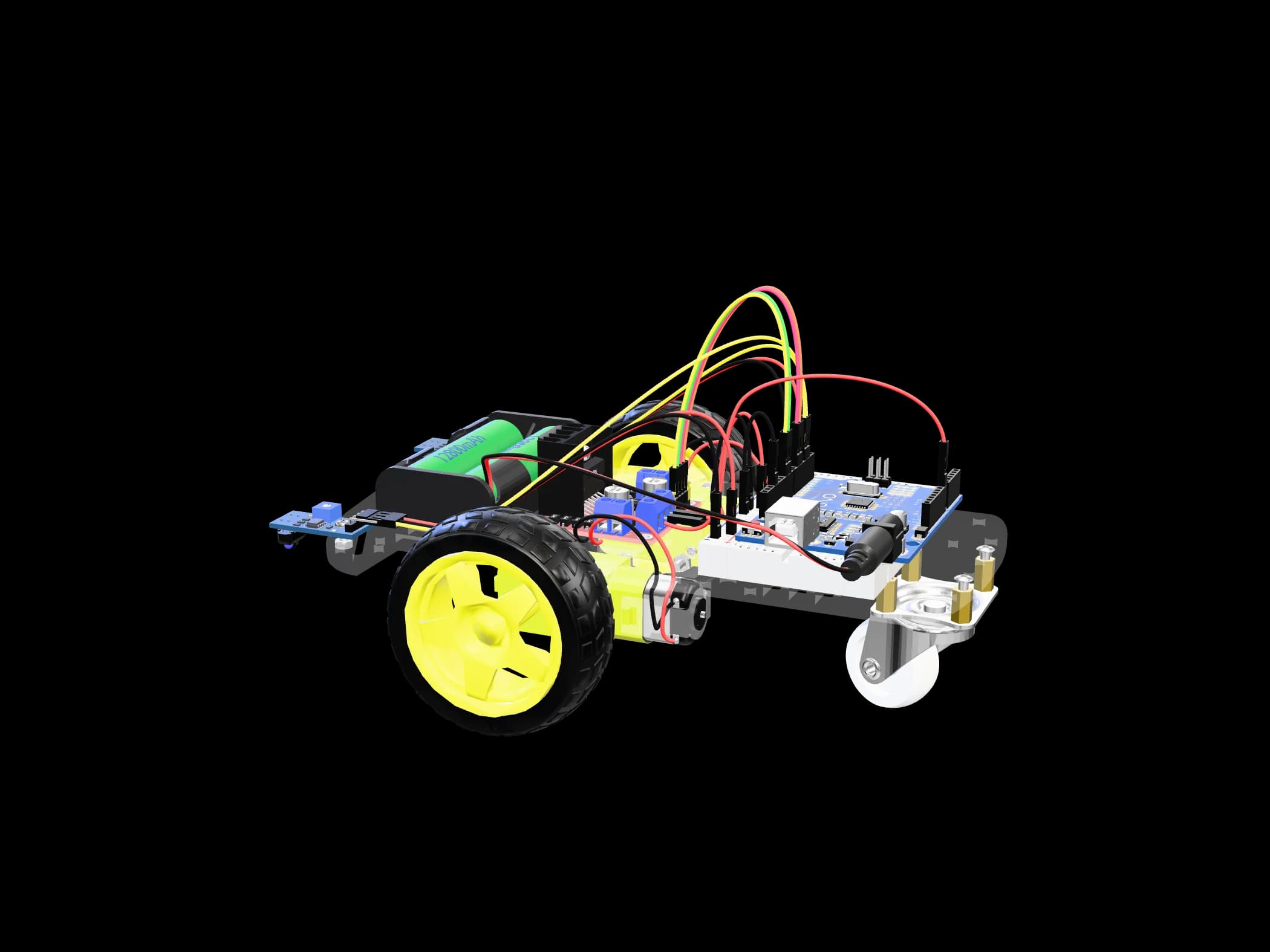
Two KY-033 sensors watch the floor: whichever way the black line drifts, the robot turns that way. Stick black electrical tape on white paper — that's your track.
- Difficulty
- Easy
- Time
- ~120 min
- Parts
- 12 parts
- Step by step
- 4 steps
- Using an infrared reflectance sensor
- A simple control algorithm
- Tuning a sensor (the potentiometer)
Parts
- 1 × Arduino UNO R3 (ATmega328P, SMD)45,000 UZS
- 1 × 2WD Robot Chassis (Plastic Deck)30,000 UZS
- 2 × KY-033 Line Tracking Sensor (TCRT5000)16,000 UZS
- 1 × L298N Dual H-Bridge Motor Driver20,000 UZS
- 2 × TT Gear Motor with Wheel (Yellow, 3–6V)30,000 UZS
- 1 × 360° Wheel: Ball Caster / Mecanum12,000 UZS
- 2 × Lithium Battery (18650 / LiPo)30,000 UZS
- 1 × Battery Holder for 18650 Cells6,000 UZS
- 1 × Jumper Wires 20 cm, Male-Female (40 pcs)12,000 UZS
You'll also need
- — A computer with the Arduino IDE (free from arduino.cc)
- — A USB cable for the UNO (the UNO SMD “+ USB cable” option)
- — A small Phillips screwdriver
- — Black electrical tape and white paper or card
Step by step
- 01
Build the car
Chassis, motors, L298N and power — as in the Robot car guide.
- 02
Mount the sensors
Fix both KY-033s at the front facing down, 5–10 mm above the floor and a little wider apart than the line (2–3 cm).
- 03
Wire and tune
Left sensor OUT → D12, right OUT → D11, VCC → 5V, GND → GND. Power up and turn each potentiometer until its LED is on over white and off over the black line.
- 04
Upload and run the track
Place the robot with the line between the sensors. If it overshoots the bends, lower SPEED.
Wiring
- Power (+)
- Ground (−)
- Signal pin
- I²C / SPI bus
- L298NENA→UNOD5 remove the jumper on ENA
- L298NIN1→UNOD7
- L298NIN2→UNOD8
- L298NIN3→UNOD2
- L298NIN4→UNOD4
- L298NENB→UNOD6 remove the jumper on ENB
- L298NGND→UNOGND common ground — required
- L298N5V→UNO5V powers the UNO from the driver
- L298NOUT1OUT2→Left motor
- L298NOUT3OUT4→Right motor
- Battery+(2×18650)→L298N12V
- Battery−→L298NGND
- KY-033leftOUT→UNOD12
- KY-033rightOUT→UNOD11
- KY-033VCC→UNO5V
- KY-033GND→UNOGND
The code
sketch.ino
// motors (L298N)
const int ENA = 5, IN1 = 7, IN2 = 8;   // left
const int ENB = 6, IN3 = 2, IN4 = 4;   // right

void motors(int left, int right) {     // -255 … 255
  digitalWrite(IN1, left >= 0);  digitalWrite(IN2, left < 0);
  digitalWrite(IN3, right >= 0); digitalWrite(IN4, right < 0);
  analogWrite(ENA, abs(left));   analogWrite(ENB, abs(right));
}

void setupMotors() {
  int pins[] = {ENA, IN1, IN2, ENB, IN3, IN4};
  for (int p : pins) pinMode(p, OUTPUT);
  motors(0, 0);
}

const int LEFT = 12, RIGHT = 11;   // HIGH = over the black line
const int SPEED = 150, TURN = 170;

void setup() {
  setupMotors();
  pinMode(LEFT, INPUT); pinMode(RIGHT, INPUT);
  delay(1500);
}

void loop() {
  bool l = digitalRead(LEFT), r = digitalRead(RIGHT);
  if (!l && !r)      motors(SPEED, SPEED);    // line between the sensors
  else if (l && !r)  motors(-TURN / 2, TURN); // line under the left one: turn left
  else if (!l && r)  motors(TURN, -TURN / 2); // under the right one: turn right
  else               motors(0, 0);            // both black: a crossing or the end
}
If something doesn't work
- It doesn't see the line: sensors too high — lower them to 5–10 mm and retune.
- It turns the wrong way: swap the sensor wires (D12/D11).
- It fails in sunlight: IR sensors dislike bright light — test indoors.
Where to go from here
- Add a third sensor for smoother turns
- Learn PID control — faster and more precise